Sensor Error Simulations
In addition to the local-level simulations supported by the toolbox, full simulations including the effects due to navigation over a rotating, spherical earth are also supported. Consider the following example simulations produced with the toolbox:
Single-Channel Simulation with Accel Bias:
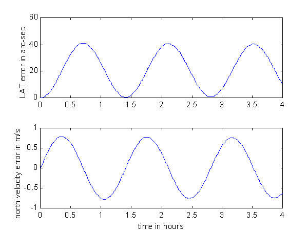
INSDEM05 is a demo included in the toolbox which performs a single channel simulation. A static vehicle is located at 45 degrees north latitude and is pointed north. A 100 micro-g bias is placed on the north accelerometer. The result of the simulation is:
According to theory, velocity error as a function of accelerometer bias is a zero-mean sinusoid with a peak value of 0.026 feet/sec per micro-g of accel bias. For 100 micro-g, then, the peak velocity error should be approximately 2.6 feet/sec or 0.8 m/s. This is observed to be the case in the above plot. Similarly, theory says that the position error should be a biased sinusoid ranging from zero up to a peak value of 0.007 nautical miles per micro-g. In this case the peak should be 0.7 nautical miles which corresponds approximately to 42 arc-seconds. Again, this is observed to be the case in the plot.
3-D Simulation with single accel bias: Accelerometer Bias Simulation
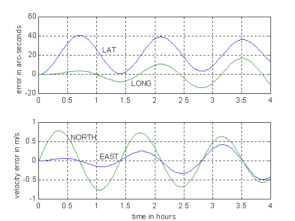
INSDEM06 is a demo included in the toolbox which extends the single channel simulation of INSDEM05 to a full three dimensional simulation. Again, a static vehicle is located at 45 degrees north latitude and is pointed north. A 100 micro-g bias is placed on the north accelerometer. The result of the simulation shows the cross-coupling effects:
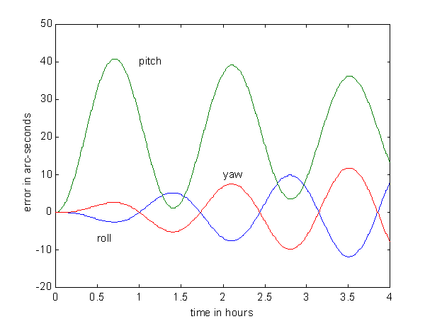
Errors can also be observed in the computed attitude. The pitch error is dominant as would be expected with a north accel bias on a vehicle pointed north. However, the error couples into the other two axes as well:
3-D Simulation with single accel bias: Gyro Bias Simulation
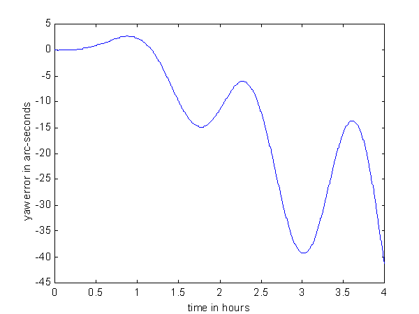
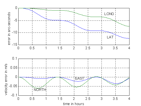
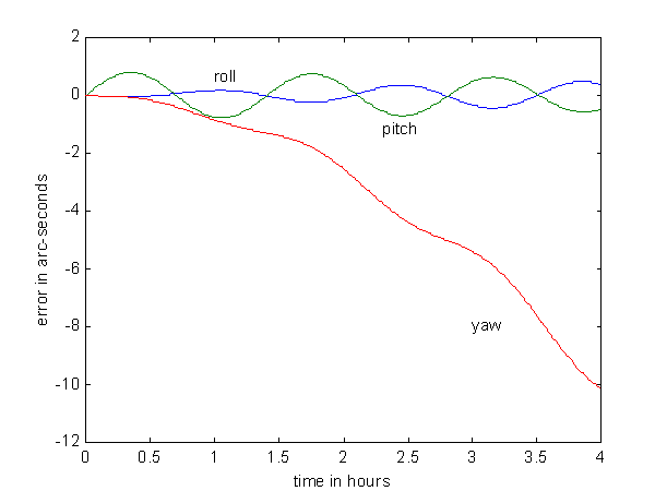
A static vehicle is located at 45 degrees north latitude and is pointed north. A bias of 0.001 degree/hour is placed on the east gyro. The Schuler oscillations are present in addition to a long term drift.
As might be expected, this is also the case with the yaw error:
3-D Simulation with single accel bias: Initial Attitude Error Simulation
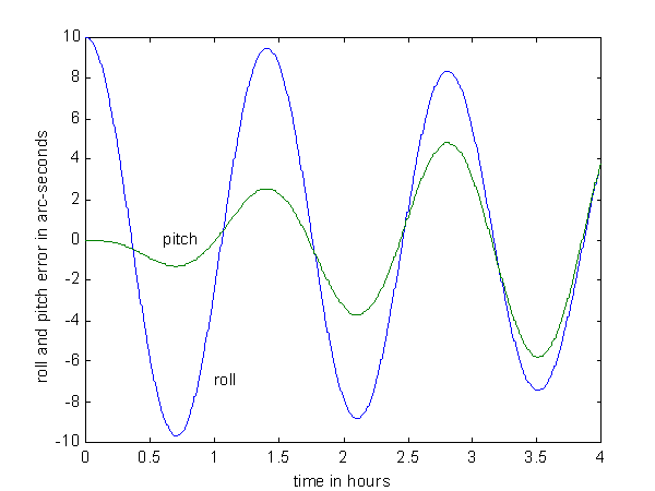
A static vehicle is located at 45 degrees north latitude and is pointed north. A 10 arc-second initial tilt (error) is placed on the north axis:
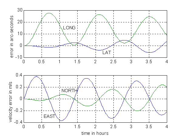
Pitch error starts off at 10 arc-seconds given the initial condition. Eventually the pitch error catches up:
3-D Simulation with single accel bias: Gyro White Noise Simulation
A static vehicle is located at 45 degrees north latitude and is pointed north. Gyro white noise with standard deviation of 0.01 degree/root-hour is placed on the east gyro only. Position and velocity errors grow as expected:
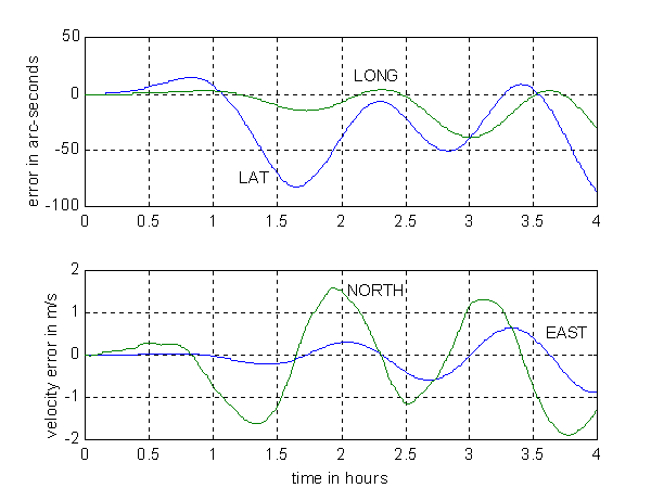
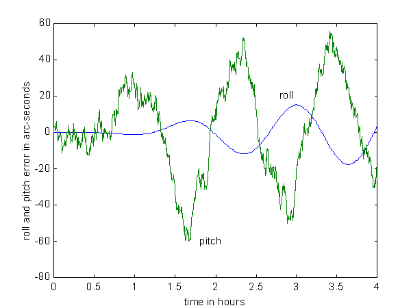
Pitch error is quite noisy which is to be expected since the vehicle is pointed north and thus the east gyro directly affects pitch. Roll and yaw errors are smooth since they are affected indirectly by the east gyro error:
Yaw error experiences a drift in addition to the Schuler oscillations:
